Out Run to USB Development/PS2 Controller Interface
Updated July 28, 2020: Described controller input, updated firmware version (5910).

Introduction
The OutRun-USB interface allows you to control and/or communicate with a Sega Out Run arcade board. With a PlayStation or PlayStation2 controller, you can control and play an unmodified ROM set for Out Run or Turbo Out Run.With bootloader ROMs installed, you can also upload and execute custom software on the board (eg. developed with the Out Run Arcade SDK), without the need of constant erasing, writing and socketing of EPROMs to iterate.
The new 2020.1 version of the SDK also features an example named 'dataxfer' that demonstrates bidirectional communication with the USB host.
You can download the full package (firmware, layout+schematics, binaries, source) here:
- OutRun-USB full package (version 1.0, build 5910)
Hardware

Overview
The interface is built around a Teensy 3.2 controller board. Chosen at the time for its USB support, ease of use and extensive amount of I/O pins. Luckily, it's still commonly available.
The Teensy's firmware runs a basic cooperative multitasker, which handles the PlayStation controller polling, USB 'socket' connection, and reading/writing the Out Run I/O pins.
")
")
Out Run's 16 digital inputs (eg. 'TEST' and 'START' buttons, gear switch) are controlled by 2 74AHCT595N shift registers, to save on Teensy output pins. Of the outputs, 4 have additional (inverting) BJT transistors, due to the presence of capacitors on the Out Run board on these specific inputs (coin switches).
Out Run's 7 accessible digital outputs connect to LEDs to complete the open-collector circuit, and in conjunction with a pull-up resistor array, voltage is measured. Please note that this does take advantage of the Teensy's 5V input tolerance.
For Out Run's analog inputs, 4 pins on the Teensy generate PWM output. These outputs are buffered, converted to 5V, and filtered by a 74HCT125N and 4x 1μF capacitors. There are 1μF capacitors on the OutRun board itself as well, but you can never be too sure.
The PlayStation controller uses the hardware SPI support of the Teensy, and just needs some pull-up resistors and a 3.3V voltage regulator.
Building the interface
The interface has been designed to be relatively easy to build. Components are through-hole only, and should be fairly common. The board is small enough to load into the free version of EAGLE, has 2 layers and no separate VIAs. With some effort to align, it is even suitable for home etching.
But you can just upload the gerber files as-is and have 10 made for $4.99 plus shipping. Be sure to give some away.
DISCLAIMER
Build, and especially, connect, at your own risk. There are no extensive safety features (fuses, diodes) present to prevent damage in the case of mis-use, plugging in things the wrong way, parts upside down or bridged solder joints. Please test and measure before hooking this up to your diamond limited series mac pro and rare, newly refurbished, Out Run board.
Make sure to label or mark the top end of your flat cable connectors, especially once you file them down to fit into the sockets.
Make sure to choose ONE power source and stick with it. If you're going to use external power (the separate power connector w/ screws), cut the VIN-VUSB line on the back of the Teensy board so that it doesn't flow back into your USB host.
Schematics, Layout

- OutRun-USB Rev.A1.1 Schematics/Layout (Eagle 6.3.0+)
Parts List
Parts list for the interface PCB, applicable for revisions Rev.A, A1, A1.1.| U$1 | Teensy 3.2, optional 28P socket (wide). |
| IC4 | 74HCT125N* |
| IC5 | LM1117T-3.3V |
| IC21, IC22 | 74AHCT595N* |
| Q21,Q22,Q23,Q24 | BC337 |
| LED1 | 3mm blue |
| LED31,LED34,LED35 | 3mm yellow |
| LED32 | 3mm red |
| LED33,LED36,LED37 | 3mm green |
| R1 | 1kΩ*, 0.25W |
| R21,R22,R23,R24 | 27kΩ, 0.25W |
| R25,R26,R27,R28 | 100Ω, 0.25W |
| R31,R34,R35 | 1kΩ** |
| R32 | 1KΩ** |
| R33,R36,R37 | 1kΩ** |
| R41,R42,R43,R44 | 1k, 0.25W |
| R51,R52,R53,R54 | 100Ω, 0.25W |
| R55 | 3k3, 0.25W |
| RA3 | 8x10KΩ |
| C1 | 100μF, 16V |
| C21,C22 | 100nF |
| C41,C42,C43,C44 | 1μF, 16V |
| C45 | 100nF |
| CN1 | Power connector w/ screw terminals. |
| CN2 | 50P IDC male 2.54mm |
| CN4 | 20P IDC male 2.54mm |
| CN5 | XH 10p 2.54mm |
| JP1 | 8x1 pin header 2.54mm |
| JP5 | 2x1 pin header 2.54mm |
*) Please be aware that the 74AHCT595Ns and 74HCT125N are connected to 3.3V outputs on the Teensy. If you must deviate from specified series, make sure that they are well behaved at 3.3V input levels.
**) See Accounting for differences in LED brightness
Accounting for differences in LED brightness

While all the LED series resistors are labeled a fairly safe 1kΩ, (perceived) brightness can differ a great deal between colors or different LED types. I recommend testing the ones you want to use out on a piece of breadboard.
These are the resistances I used with some diffuse 3mm LEDs I got in a kit off AliExpress (which came with absolutely no data sheets):
| Color | R | VF | I |
| Red | 3kΩ | 1.87V | 1.1mA |
| Yellow | 2kΩ | 1.96V | 1.6mA |
| Green | 270Ω | 2.17V | 11mA |
| Blue | 3kΩ | 2.63V | 0.85mA |
Please do pay attention to the 10kΩ pull-up resistor array when deviating significantly (upwards) from these values.
USB or external power
There are 2 ways to properly power the interface:Power via USB. Your USB host will power the rest of the interface. This is ideal for tinkering with the interface with no game board connected. The downside is that the length/quality of the USB cable may affect the analog input range (off-center steering), and that you always need a USB host (no stand-alone PS2 controls). This is the default configuration if your Teensy board is new.
Power via external +5V supply. In this configuration the power for the entire interface, including the Teensy, is provided by an external +5V source, probably the one that also powers your game board. This way, you can control the game without having to be hooked up to a USB host. The downside is that your interface will need to have external power turned on, if you want to be able to connect to it from a host machine.
To use this configuration, cut VIN from VUSB as pictured on the instruction card that came with your Teensy:

Again: make sure to choose ONE power source and stick with it. If you're going to use external power (the separate power connector w/ screws), cut the VIN-VUSB line on the back of the Teensy board so that it doesn't flow back into your USB host.
Assembly notes / tips
- Start with the lowest/flattest components (eg. resistors), so you can rest the back on your workspace.
- Note the orientation of the LEDs, resistor array, ICs and electrolytic capacitors. The digital I/O LEDs are required to complete the digital input circuit, and will not operate with the LEDs reversed.
- You can use the end of a match (without head!) to neatly space the 3mm LEDs away from the board.
- You can use a flat-cable connector as additional heat sink for the headers on the PCB while soldering. It'll also keep the pins aligned.
- Socket the Teensy if you want to reuse it later, or want/need to be able to access the VIN/VUSB trace. A wide 28p DIP socket works.
- You can use a small vise to press the connectors onto your flat cables. File off the middle notch at the OutRun end, and label the top.
- There are pre-made 20P flat cables available on AliExpress, as well as pre-wired XH connectors.
Firmware
Flashing the firmware
- OutRun-USB firmware binaries (version 1.0, build 5910)
If you don't have TeensyDuino installed, get it first, or if you don't intend to do any development anyway, use the Teensy loader application from pjrc.com.
Once running, use the File → Open menu option to browse to the OutRun-USB firmware .hex file.
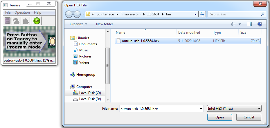
If your device is not detected (for instance, when you are currently running a non-debug version of the OutRun-USB firmware on), press the button on the Teensy to go into bootloader mode. This will allow you to program it, either in automatic mode or with the Operation → Program menu commands.
Once you reboot the Teensy with the OutRun-USB firmware, the orange LED on the Teensy should come on within a second (indicative of polling the PS2 controller, or at least looking for it).
You can test the USB connection with orboot-usb (included):
c:\outrun\bin>orboot-usb -debug
Connected to interface.
Device firmware version: 1.0, "OutRun-USB 1.0 (build 5910)"
Listening for debug output. Press [escape] to exit.
Building the firmware from sources
- OutRun-USB sources (version 1.0, build 5910)
Using Arduino IDE
First download and install TeensyDuino and, if you don't already have it installed, the Arduino IDE.
If you think you can stomach working with the Arduino IDE, you can load the firmware-scheduler.ino sketch. Configure your board as follows:

Board: "Teensy 3.2 / 3.1" USB Type: "Raw HID" CPU Speed: "72 MHz" Hit the Verify button to compile the sketch, and Upload to flash it to the connected Teensy device.
As the Arduino IDE doesn't have any concept of build configurations, the binary produced by it will match the release version as built by make.bat (see below).
-
Using make.bat
Alternatively, on Windows host machines, you can use the make.bat script located in the same folder. If the script can't find your Arduino/TeensyDuino installation, you can either externally set the ARDUINO_PATH environment variable to point to the Arduino folder, or edit the search paths near the top of the batch script.
Firmware build configurations
There are - at this time - three build configurations:
| debug: | Has the most extensive debug logging via USB serial. DEBUG_ASSERT() expressions are evaluated and upon failure, the firmware is halted, and will log the failure via serial, and will blink the offending line number on the built-in LED on the teensy board (decimal; short blip=0). |
| release: | Still has USB serial logging and DEBUG_ASSERT handling, but less verbose logging. |
| final: | No serial over USB present, no logging. No DEBUG_ASSERT evaluations. |
You can either pass debug or final as a parameter to make.bat. By default, the release configuration will be built.
Alternatively, when building from Arduino IDE, you can either set the _DEBUG macro for debug or NDEBUG macro for final in build_config.h.
Some additional debugging and trace features can be configured in firmware_config.h.
Additional Software
Bootloader ROMs
- Bootloader ROMs (version 0.9D)
- Bootloader sources (version 0.9D) — build with the 68000 cross compiler.
The bootloader replaces the main and - optionally - secondary startup ROMs (either 2 or 4 ICs) and puts the Out Run board in a receptive state on startup, allowing you to upload custom code to its memory and execute it.
The bootloader images should be written to 27C512 type EPROMs.
If you install only the first two ICs for the main CPU (118 and 133), the secondary CPU will still try to run, but since it can only access its own working memory and the road registers, it may not conflict with your own program. In this case, the bootloader background will be grayed out as a reminder. If all four are installed, the background will be blue.
Communication is done over mostly unused digital input button and output pins; the protocol used is very similar to IEEE 1284 compatibility mode. The notable differences being in the timing - due to lack of interrupts on the input pins.

orboot-usb
orboot-usb is the host-side program that communicates with the Out Run board through the USB interface, and enables uploading custom code or data if the bootloader ROMs are present.
As its arguments, you can specify one or two binary files with a maximum of 32KB in CPU order. The first binary image will be uploaded to main CPU memory, the second - optional - binary to secondary (road) CPU memory. After the upload completes, execution will continue from start vectors specified in the uploaded images, i.e. your program will start.
The -debug option will keep orboot-usb running in transfer mode; this allows for bidirectional communication while your program is running. Keyboard input from the host is sent to the Out Run board, and your program can send data back. Please refer to the dataxfer sample and/or samples/common/comm.cpp implementation for more details.
You can also run in -debug mode without any binaries to just test the connection, or to (re)connect to an already running program.
Windows binaries are provided, but orboot-usb will also compile for and run on Linux (including Raspbian) and MacOS. The source code is included with the orboot-usb package. A Visual Studio solution is included, as well as a makefile for the other supported platforms.
Linux (Raspbian) users may need to add a udev rule in order to access the interface with regular user access rights.
PlayStation2 Controller Input
The interface converts PlayStation and PlayStation2 (Dual Shock 2) serial data into the analog and digital inputs on the Out Run PCB.
While digital and analog PlayStation controllers are supported, their limited analog capabilities do not make them the best choice. Use a PlayStation2 controller for full analog support.
| Action | Controller Button(s) |
| Steering | Left analog stick (horizontal) D-pad left, right |
| Acceleration |  , R2 , R2 |
| Brake |  , L2 , L2 |
| Turbo Boost* |  |
| Low Gear | L1 |
| High Gear | R1 |
| Start | Start |
| Test | Select + L2 |
| Service | Select + L1 |
| Coin 1 | Select + R2 |
| Coin 2 | Select + R1 |
*) Turbo Out Run only.
Acknowledgements
Development of this project has been a never ending rabbithole where many a road block resulted in a whole new order of complexity. It's been at times both tedious and fun.
I'd like to thank those that already have got (or even built) these interfaces during its long development time for their patience, confidence and understanding, but also for the renewed energy that sparked from their interest.
orboot-usb uses hidapi by Signal 11 Software, with modifications by djpnewton.
The firmware will link with TeensyDuino core libraries, many if not all by Paul Stoffregen/PJRC.COM.
The schematic/board layout makes use of Eagle libraries by Rembrandt Electronics and Andrey Ovcharov (see libs folder).
